TLP Tester
Transmission Line Pulse
1.Purpose for TLP
TLP means Transmission Line Pulse. When the electric charge in the coaxial cable discharges, the rectangle
waveform is generated.
We can examine the protection circuit characteristics of semiconductor using this phenomenon.
The important factor is the rise time of the rectangle waveform.
The protection circuit characteristics depends on the faster rise time or slower one of the rectangle waveform.
Therefore, it is very important to have the rise time changed from high frequency to low frequency.
A rise time less than 200 [ps] is required in TLP tester as an ideal waveform.
2.TLP Theory
The following three methods are used to get the TLP wave form
(1)TDR(Time Domain Refraction)
TDR means the method that picks up the reflection waveform from DUT.
(2)TDT(Time Domain Transmission)
DUT means the method that picks up the waveform passed through DUT.
(3)TDTR(Time Domain Transmission and Refraction)
TDTR means the combination method of above TDR and TDT.
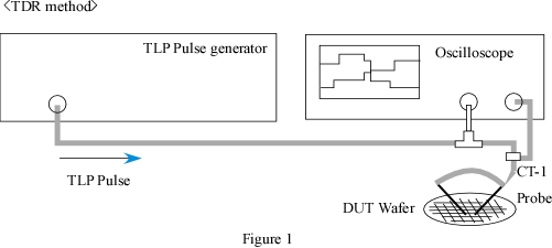
An oscilloscope is connected directly on the discharge circuit for the observation of voltage waveform, and a
current probe inserted in the the discharge circuit is used to get current waveform as well.
In the TDT method, the position of An oscilloscope and DUT is opposite in Figure 1 In the test of TLP, The
rectangle's rise time can be changed by using the filter.
However, the pulse width is able to be changed by only adjusting the length of coaxial cable.
Figure 2 shows the composition for TLP circuit.
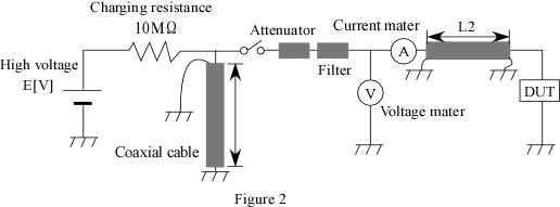
Pulse width T=2L1/V T: Pulse width (ns), L1: Length of coaxial cable (mm)
V = 2.0 * 108m/s
[Example]
If L1 is 20 (m), the pulse width T becomes 200 (ns)
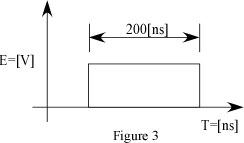
The rectangle waveform, Figure 3 can be observed with the voltage meter in Figure 2.
The voltage mater in Figure 2 means an oscilloscope.
this waveform is that all energies are consumed by DUT
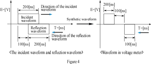
If L2 is 10mm and DUT is short, the incident waveform and reflection waveform occur as shown in the following
figure.
The relations between incident waveform and reflection one is the left figure in figure 4.
And also the waveform shown in voltage meter (oscilloscope) the right figure in Figure 4.
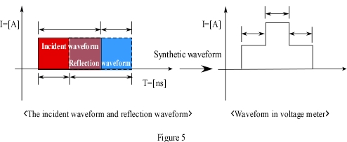
The current waveform shown in Figure 5 can get by using current meter.
The relations between incident waveform and reflection one is the left figure in figure 5.
The waveform shown in current meter (current probe) the right figure in Figure 5.
|
